| |
~@Com~ On the 'Net since 1994 |
Black Jack Computers Email |
|
Links: Photo Gallery | Blackjack Project | Roulette Project | Roulette Timing | KIM-1 (6502) | Correspondence |
||
| |
~@Com~ On the 'Net since 1994 |
Black Jack Computers Email |
|
Links: Photo Gallery | Blackjack Project | Roulette Project | Roulette Timing | KIM-1 (6502) | Correspondence |
||
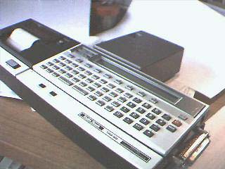
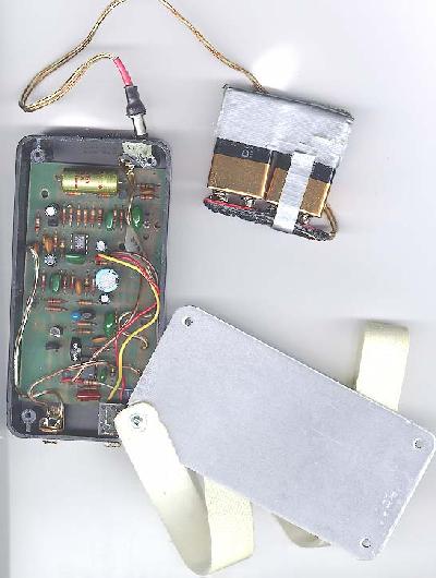
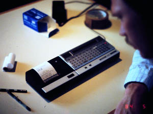
Before we did anything, we gathered data. At first we used our home-made "KIN" computer to time the ball and rotor (wheel) surreptitiously -- in a casino. The KIN computer was interfaced with a speech synthesizer; this hardware was left over from a previous project, the Black Jack machine. With the help of my friends Rita and Richard, we three timed the ball and wheel in a casino. (At the time we did not own a roulette wheel.) I wore all computer hardware concealed on my person; I think Rita had the our cassette recorder in her purse. One of the timing switches (Rita's switch) was attached to the rear of my belt. Rita would stand beside me and embrace me with one arm form behind, inside my overcoat, so that she could enter the revolution times of the rotor with the belt switch. I timed the ball revolutions by using a switch in my trouser pocket. The speech synthesizer spoke the revolution times onto a tape recorder. We also spoke the landing pocket onto the recording. The speech output from the computer was temporally compressed so that it had a high pitch when played back at normal speed. This compression was made so that everything would be recorded quickly in real time. A rheostat inserted into the recorder's drive motor allowed for slowing its motor speed, enabling us to play the tape so that it could be understood. Listen to a sample. This data retrieval was time consuming, so we abandoned it, after having purchased the Radio Shack "PC2" (and the clone: Sharp PC-1500 Pic) computer pictured here.
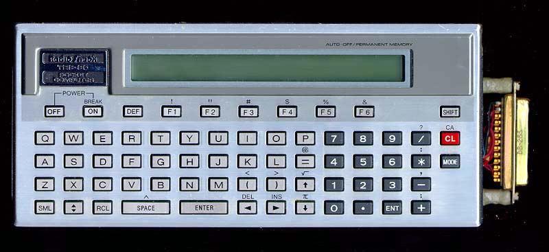
Next, we did our analysis and prediction in two phases. In the first phase we used a concealed computer (Radio-Shack PC2) to gather data on ball and rotor speed, using a computer program that could time the ball and wheel speeds (revolution times). No attempt at prediction was made in this phase. The computer ran BASIC (WikiPedia)-- the timing routines were loaded as machine language, using "pokes". For each trial, data representing revolution times and the resulting winning number were then uploaded to an APPLE-II computer for analysis, Via a modem. The object of the analysis was to smooth the data points thus obtained and to determine the parameters of the decay curves for the ball and for the rotor.
The PC2 computer was modified to interface with an APPLE II computer, (for uploading the timing data for analysis) as well as with with a speech synthesizer to announce the predicted winning number (in the second phase). Having determined these parameters from the uploaded data on the APPLE II, we typed them into the PC2 computer. This information is unique to each wheel and was required top load the prediction program. (Shown here is the PC2 computer attached to its docking station. The docking station had a four-color plotter (left) and a modem (black box at rear).
Radio-Shack PC2 computer Wiki
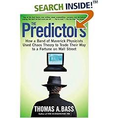
If you are seriously considering
this, you will find this book of
IMMENSE interest. (I promise :)It's the story of techno-nerds
who did a Black Jack project
using similar computer equipment
as THIS.
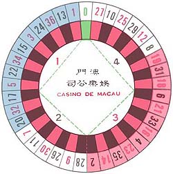
The single-zero wheel is used in Asia
and in Europe. This is picture is freely
given at roulette tables at the Lisboa Casino.
Our wheelWe required two experimenters for this operation during play; one to clock the ball and wheel, to enter the winning number and position on the rim of the wheel (between 12 o'clock and and 12 o'clock) Another experimenter placed the bets at the table. Communication was via infrared.
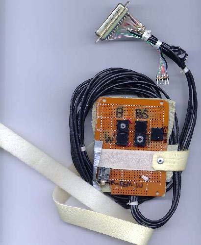
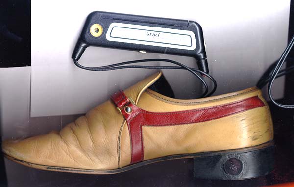
During the second phase, at the roulette table, the actual predictions were made by the PC2 computer . The speech synthesizer transmitted the wining number to the second player via an infra-red link built into each of the two experimenter's shoes.
|
|
||||||||
|
Just for fun, here is a link to a web page which lets you write programs in AppleSoft BASIC. Basic is what we used to analyze our Roulette data on the Apple II.
|
||||||||
|
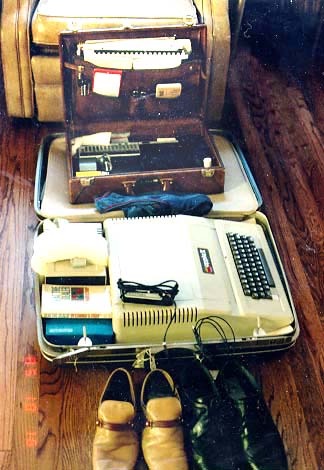
Travel kit.
A large suitcase contains
|
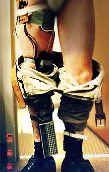
Everything which was worn by the
|
|||||||
|
One
experimenter's shoe. |
This work was done by my
then-friend
Richard and me. |
|||||||
|
|
||||||||
|
|
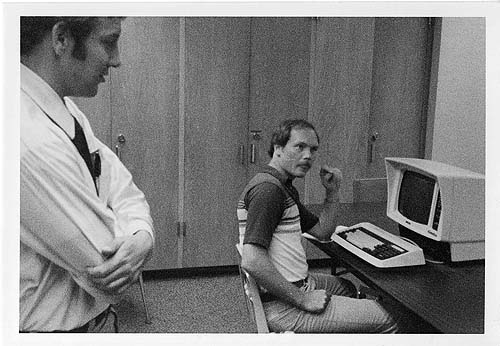
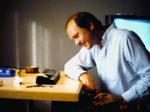
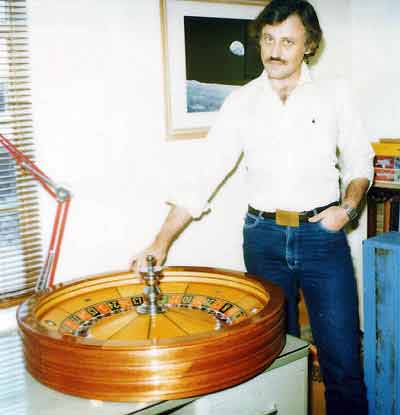 A picture of me ca 1984. John Huxley Wheel. This wheel is FOR SALE. |
|||||||
|
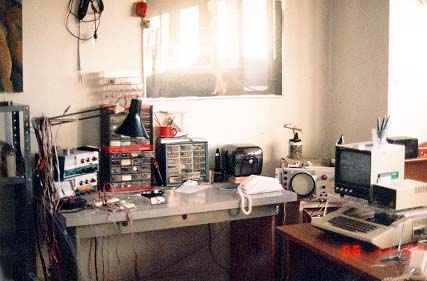
Experimental setup for accurate measurement in the lab. |
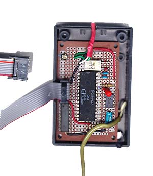
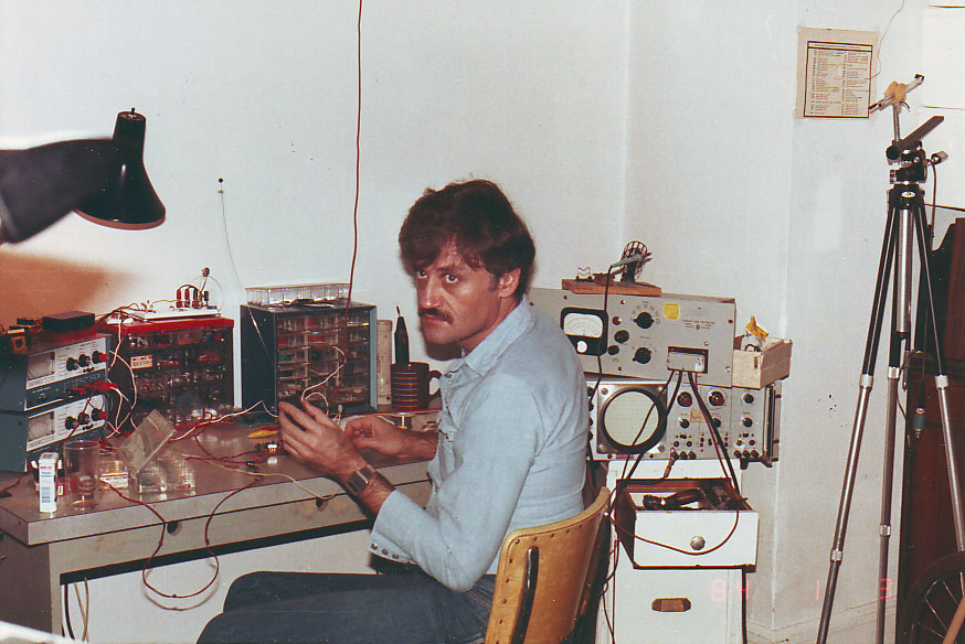
 Black Jack predicting computer. The homemade KIN computer is inserted into socket on a test-kludge box (right); the KIM computer is in its housing (center), ca. 1981. Photo: MINOX 8mm film. |
|||||||
|
( This casino quality double-zero John Huxley roulette wheel is for sale, by the way :) |
||||||||
 |
 |
|||||||
|
|
||||||||
|
||||||||
|
||||||||
Copyright @Com 2012. Last updated 09.04.2015